A Low Pass Filter (LPF) is used after an RF amplifier to prevent the transmission of harmonics. This design, which appears on Free Radio Berkeley's web-site, is unusual in that it does not use discrete capacitors. In this design, the capacitive elements of the filter been made up by the capacitance formed by large areas of copper with a ground plane underneath. The filter is a 9 pole Chebyshev (each reactive element contributes one pole).
As usual in plans available from the web (see advice on building plans from the web), various crucial details are not made sufficiently clear. These include
I made the following changes to the design:
The purpose of modifications 3 and 4 is to reduce the inductive coupling between adjacent inductors. This significantly improves the amount of final attenuation obtainable in the filter
The small signal insertion and return losses were measured using a HP 8714C network analyser. As built, the filter had a 15dB return loss (VSWR 1.433 : 1). This would be acceptable in practice. Tuning the inductors by squeezing the coils tighter and pulling them apart did not yield any improvement, but by introducing some extra capacitance on C2 and C4 by adding extra areas of board, the return loss could be improved to -20dB (VSWR 1.222 : 1) across the band.
Handy hint |
Frequency |
Before Tuning |
After Tuning |
||
| Insertion Loss (S21) dB |
Return Loss (S11) dB |
Insertion Loss (S21) dB |
Return Loss (S11) dB |
|
| 88 | -0.75 | -15.8 | -0.67 | -20.0 |
| 108 | -1.05 | -18.6 | -1.02 | -21.8 |
If a network analyser had not been available, I could have optimised the input return loss by applying RF power to the filter (with the filter correctly terminated into a dummy load) via a Bird 43 directional RF power meter with a 5W 50 to 125MHz plug-ins to monitor the reflected power. Tune the filter elements to minimise the reflected power, this will maximise the transmitted power and is generally the best way to optimise a filter.
The worst case for a low pass filter is the second harmonic rejection at the bottom end of the band, 2 x 88 = 176MHz. At this frequency the filter has a respectable 50dB of rejection. This means even using a transmitter with high level of 2nd harmonic, for example -25dBc, the harmonic rejection at the output of the filter will be around -75dBc, which is very good. Frankly 9 poles is a bit over the top, a carefully designed 7 pole should do the job, and have a lower loss. By the time we get to the 3rd harmonic, rejection is in the order of -70dB, and stays at this level up to 600MHz. Up around 1GHz, (not plotted) the rejection does creep back up to around 50dB, this is due to inductive coupling between the inductors. To improve this would require screening the inductors from each other. No decent power amplifier should be generating appreciable amounts of harmonic energy up at these frequencies anyhow.
88W of RF at 104.9MHz were applied to the filter. 72W were measured after the filter (0.87dB loss), dropping to 66W over the next ten minutes as the filter warmed up. 66W output from the filter for 88W drive corresponds to a filter 1.25dB loss (10 log10 [66/88]). The temperature of the filter assembly was now in the region of 60°C, not surprising as it was dissipating 22W of heat.
Four effects contribute to filter loss:
For this filter, the dominant loss is the dielectric loss in the capacitors, as FR4 (the name of standard printed circuit board material) used to form the capacitors is quite lossy at VHF frequencies. Worse still, the loss of FR4 increases with temperature, so that loss and temperature force each other upwards.
This temperature rise places a practical limit of the power handling of the filter. I tested the unit in free air. Mounting the filter properly, screwed to the base of a metal enclosure, would provide a better thermal path to stop the filter becoming excessively hot. But really, having gone to the trouble of generating say 100W of RF power, you don't really want to loose 25W of it as heat in your filter. I don't recommend using this filter with more than 50W or so. This would result in 12.5W of heat to dissipate.
 The loss of the filter could be improved by using a better printed
circuit board material, for example Rogers 4003, unfortunately these materials are not
readily available. It would be far easier to use conventional wrapped mica RF capacitors,
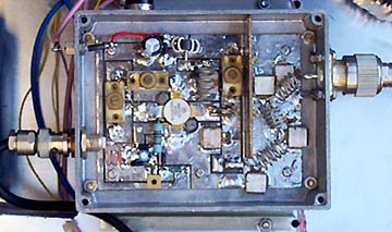
like those manufactured by Semco and Unelco. For comparison, on the right hand side of the
image to the right can be seen a 7 pole 0.1dB ripple Chebyshev low pass filter,
constructed from 18 SWG tinned copper wire inductors and Semco capacitors. This
filter typically has a pass-band insertion loss of less than 0.15dB and can easily handle
power in excess of 100W.
The loss of the filter could be improved by using a better printed
circuit board material, for example Rogers 4003, unfortunately these materials are not
readily available. It would be far easier to use conventional wrapped mica RF capacitors,
like those manufactured by Semco and Unelco. For comparison, on the right hand side of the
image to the right can be seen a 7 pole 0.1dB ripple Chebyshev low pass filter,
constructed from 18 SWG tinned copper wire inductors and Semco capacitors. This
filter typically has a pass-band insertion loss of less than 0.15dB and can easily handle
power in excess of 100W.
The mismatch at power was measured using a Bird 43 directional RF power meter fitted with 100W and 5W plug-ins, the meter between the RF source and the filter. For 88W forward power, the reflected power was 1W. This corresponds to a filter input return loss of -19.4dB (10 log10 [1/88]), which is good. Using a Bird power meter lends itself to working in return loss in dBs, rather than VSWR (voltage standing wave ratio). To my mind VSWR belongs to a bygone age with cycles-per-second (now Hertz). Working in return loss in dBs allows you to readily convert reflected powers back and forth to return loss in dBs, (assuming you understand dBs) using a calculator. For example, a good aerial is one that has a VSWR of a less than 1.5:1. What does this actually mean? Using a conversion equation, or more simply a conversion table, we can find that this is equivalent to a return loss of 14dB. So for a 100W (50dBm) transmitter running into this aerial, the amount of power reflected back to the transmitter from the aerial is 50 - 14 = 36dBm, or 4W.
For
Against
[ How to be a Community Radio Station Home Page | Introduction to Community Radio Station Electronics ]